How to wire the Electrical Motor Controller?
The electrical motor controller can be divided into the motor rotation controller and the motor speed controller. The motor rotation controller is a kind of DPDT solid state relay, which can be used to replace the complex electromagnetic relay system and directly control the rotation direction of the electrical motor through digital signals. The motor speed controller can control the rotation speed of the DC electrical motor by adjusting its input power. Through this article you will learn the circuit wiring diagrams of our electrical motor controllers.
You can quickly navigate to the chapters you are interested in through the Directory below, and the Quick Navigator on the right side of the browser.
CONTENTS
§1. How to wire AC Motor Rotation Controller? |
§2. How to wire DC Motor Rotation Controller? |
§3. How to wire DC Motor Speed Controller? |
§1. How to wire AC Motor Rotation Controller?
1.1 Single Phase AC Motor Rotation Controller
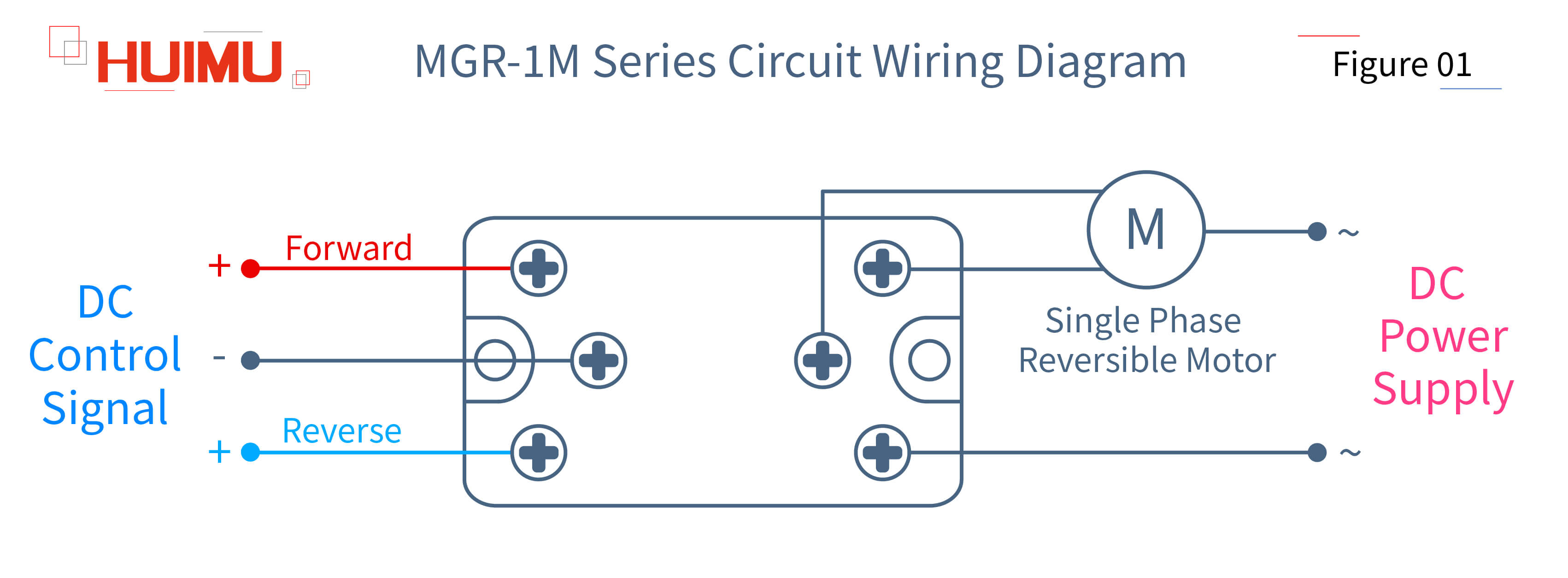
● MGR-1M Series
The single phase AC motor rotation controller, also known as single phase AC bi-directional solid state relay and single phase AC forward and reverse switch, is used to control the forward and reverse direction of single phase AC reversible electrical motor through DC control signals. The input terminals of the single phase AC rotation controller are connected to the DC control signals, one of which is a common terminal, and the other two are used to receive the direction control signal from the control device. The single phase AC motor rotation controller has three output terminals, one of which is connected to the AC power supply and the other two are connected to a single phase AC reversible electrical motor.
1.2 Three Phase AC Motor Rotation Controller
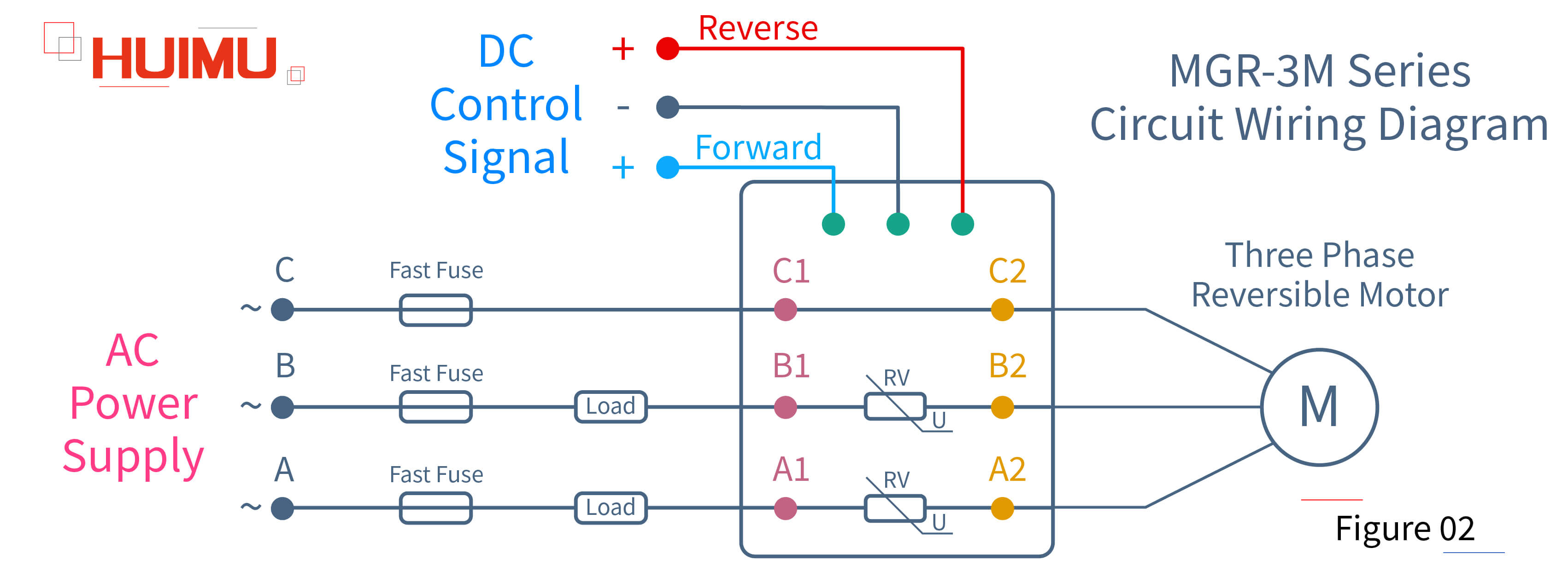
● MGR-3M Series
The three phase AC motor rotation controller, also known as three phase AC bi-directional solid state relay and three phase AC forward and reverse switch, is used to control the forward and reverse direction of three phase AC reversible electrical motor through DC control signals. The input terminals of the three phase AC rotation controller are connected to the DC control signals, one of which is a common terminal, and the other two are used to receive the direction control signal from the control device. The output terminals of the three phase AC motor rotation controller are divided into two groups, one of which (A1, B1, C1) is connected to the three phase power supply, and the other (A2, B2, C2) is connected to the three phase AC reversible electrical motor.
§2. How to wire DC Motor Rotation Controller?
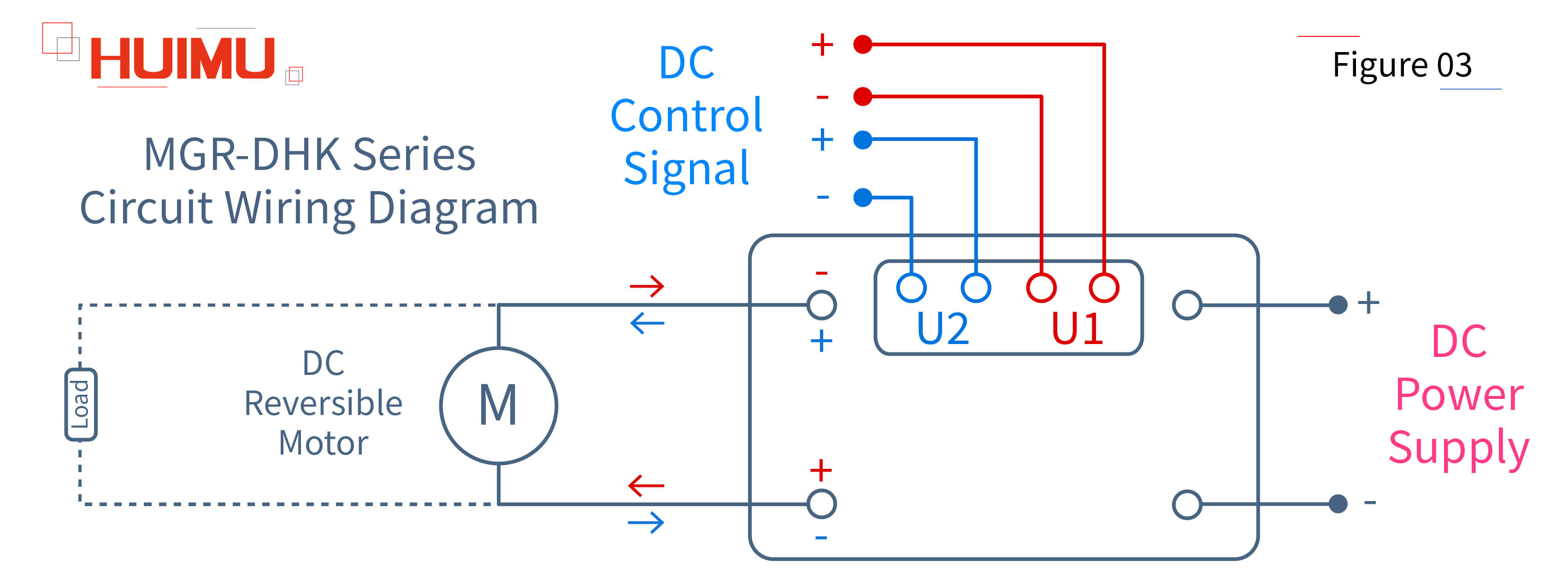
● MGR-DHK Series
The DC motor rotation controller, also known as DC bi-directional solid state relay and DC forward and reverse switch, is used to control the forward and reverse direction of DC reversible electrical motor. Compared to the AC motor rotation controller, the wiring of the DC motor rotation controller is more flexible. The input terminals of the DC motor rotation controller are divided into two groups (U1 and U2), which are perfectly symmetrical, that is, if U1 is defined as a forward signal, then U2 is the reverse signal and vice versa. The output terminals of the DC motor rotation controller are also divided into two groups, one of which is connected to the DC power supply and the other is connected to the DC reversible electrical motor. It should be noted that the two output terminals connected to the DC reversible electrical motor are also perfectly symmetrical, that is, when U1 is working, the current will flow from the red "+" to the red "-", and when the U2 is working, the current will flow from the blue "+" to the blue "-". Of course, the DC motor rotation controller is not limited to controlling the DC reversible electrical motor, if a DC load has different working states under the two signals of U1 and U2, then it can also be controlled with this DC motor rotation controller.
§3. How to wire DC Motor Speed Controller?
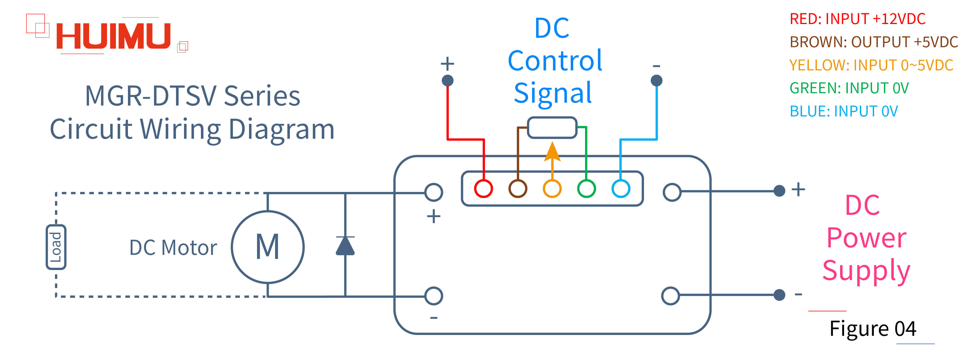
● MGR-DTSV Series
The DC motor speed controller, also known as DC motor speed regulation solid state relay, DC thyristor motor speed control switch and DC motor governor, is used for stepless control of the DC variable speed electrical motor. The input terminals of the DC motor speed controller can be divided into two groups, one of which (red and blue) is used to supply the DC control signal and the other (brown, yellow, and green) is used to form the potentiometer. The output terminals of the DC motor speed controller are divided into two groups, one of which is connected to the DC power supply and the other is connected to the DC variable speed electrical motor. The DC variable speed electrical motor has the advantages of wide speed regulation range, small energy loss during speed regulation, large starting and braking torque, easy control and high reliability. Therefore, the stepless speed regulation of the DC variable speed electrical motor can be realized by adjusting its operating voltage through the potentiometer. It should be noted that a diode should be connected in parallel to the DC variable speed electrical motor in order to prevent it from being burned by wiring errors. Of course, the DC motor speed controller is not limited to controlling the DC variable speed electrical motor, but can also be used for the DC load whose output power can be continuously adjusted by adjusting its operating voltage.

Get in touch with us now!
Please select the message type and fill in the contact form in English. Thank you!
*Please check the trash box of your mailbox, if you do not receive our email.


