How to wire the Solid State Voltage Regulator?
The solid state voltage regulator can adjust the power supply voltage to a voltage value suitable for load operation through its internal voltage regulation circuit. According to the voltage regulation mode, the solid state voltage regulator can be divided into the potentiometer type solid state voltage regulator, the analog signal type solid state voltage regulator, the digital signal type solid state voltage regulator and the external transformer type solid state voltage regulator. The potentiometer type solid state voltage regulator adjusts the voltage by means of an external potentiometer. The analog signal type solid state voltage regulator adjusts the voltage by means of a control signal with a continuously variable voltage. The digital signal type solid state voltage regulator adjusts the voltage by means of pulse digital signal. The external transformer type solid state voltage regulator adjusts the voltage through the potentiometer based on the reference voltage provided by the external transformer. According to the control mode, the solid state voltage regulator can be divided into automatic control signal type solid state voltage regulator and manual control signal type solid state voltage regulator. The automatic control type solid state voltage regulator automatically adjusts the voltage by the control signal from the control device. The manual control type solid state voltage regulator adjusts the voltage by manually adjusting the potentiometer. Sometimes, we integrate the solid state voltage regulator and its peripheral circuitry into the solid state voltage regulator module to reduce the size and increase the convenience and stability.
You can quickly navigate to the chapters you are interested in through the Directory below, and the Quick Navigator on the right side of the browser.
CONTENTS
§1. How to wire Solid State Voltage Regulator? |
§2. How to wire Solid State Voltage Regulator Module? |
§1. How to wire Solid State Voltage Regulator?
1.1 Single Phase AC Solid State Voltage Regulator
● MGR-R Series
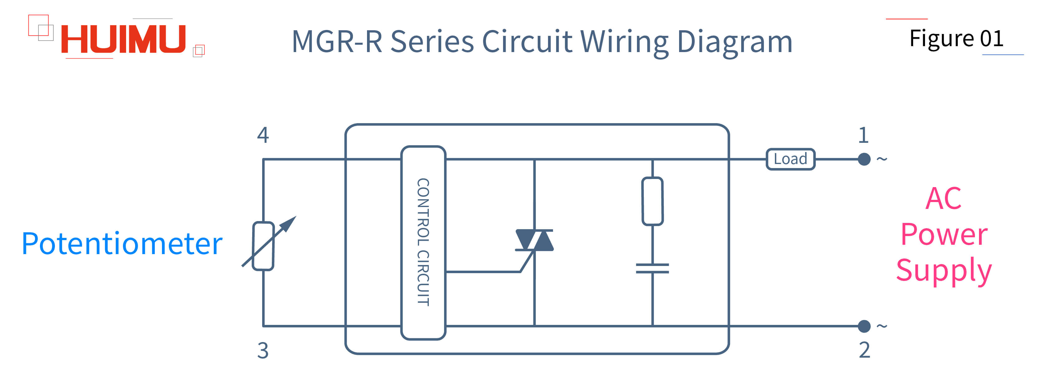
The potentiometer type single phase AC solid state voltage regulator is available in standard package. The two input terminals of the potentiometer type single phase AC solid state voltage regulator are connected to an external potentiometer. The two output terminals of the potentiometer type single phase AC solid state voltage regulator are connected to the AC power supply and the load. The load voltage can be regulated and controlled by adjusting the external potentiometer.
● MGR-HVR Series
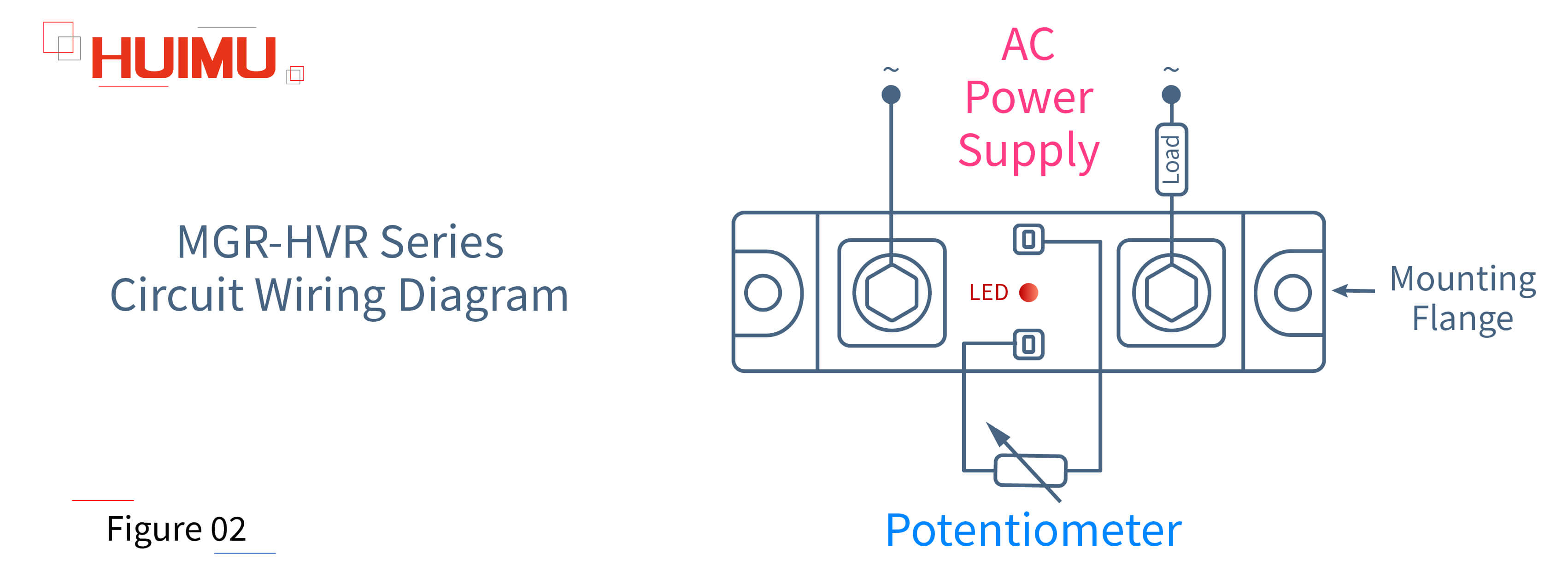
The potentiometer type industrial single phase AC solid state voltage regulator is available in industrial package. The two input terminals of the potentiometer type industrial single phase AC solid state voltage regulator are connected to an external potentiometer. The two output terminals of the potentiometer type industrial single phase AC solid state voltage regulator are connected to the AC power supply and the load. The load voltage can be regulated and controlled by adjusting the external potentiometer. The potentiometer type industrial single phase AC solid state voltage regulator is installed in the application device by the mounting flange.
● MGR-1VD Series
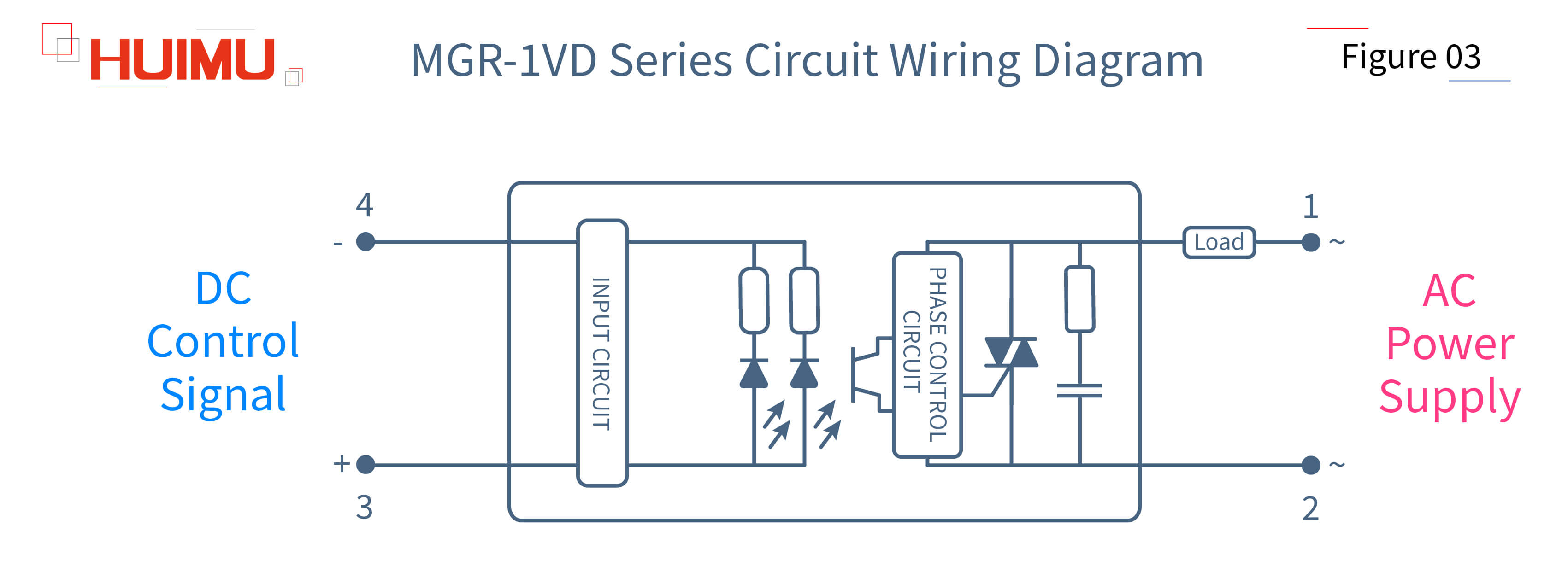
The analog signal type single phase AC solid state voltage regulator is available in standard package. The two input terminals of the analog signal type single phase AC solid state voltage regulator are connected to the signal output terminals of the analog control signal device. The two output terminals of the analog signal type single phase AC solid state voltage regulator are connected to the AC power supply and the load. The control signals of the analog signal type single phase AC solid state voltage regulator are divided into E (0-5VDC), F (0-10VDC) and G (4-20mA) types. The load voltage can be regulated and controlled by adjusting the analog signal.
● MGR_DV Series
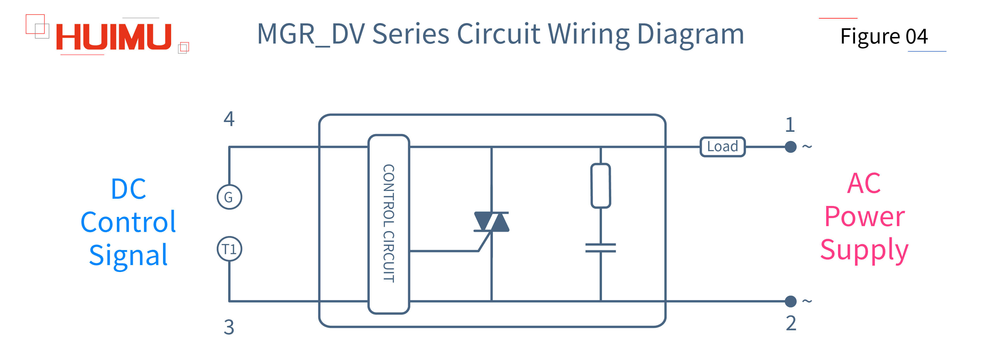
The digital signal type single phase AC solid state voltage regulator is available in standard package. The two input terminals of the digital signal type single phase AC solid state voltage regulator are connected to the signal output terminals of the digital control signal device. The two output terminals of the digital signal type single phase AC solid state voltage regulator are connected to the AC power supply and the load. The control signal of the digital signal type single phase AC solid state voltage regulator is pulse voltage signal (step voltage signal). The load voltage can be regulated and controlled by adjusting the digital signal.
● MGR-EUV Series
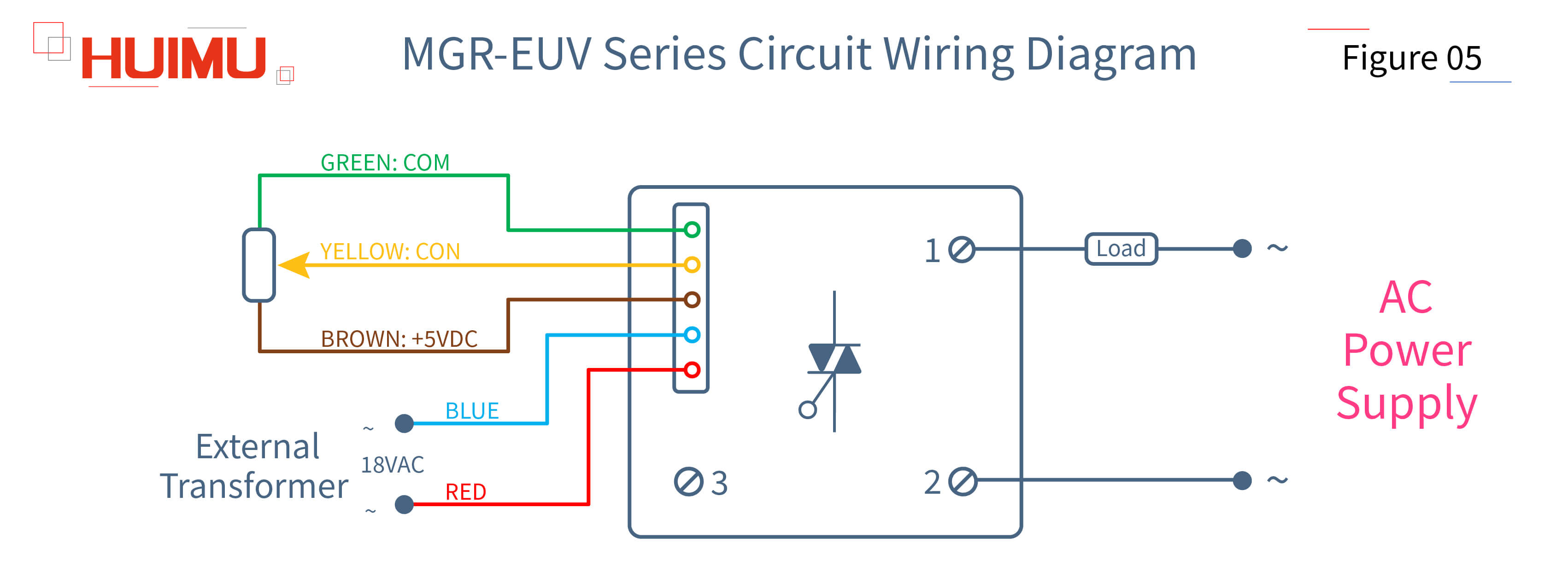
The external transformer type single phase AC solid state voltage regulator is available in standard package. The input terminals of the external transformer type single phase AC solid state voltage regulator can be divided into two groups, one of which (red and blue) is connected to an 18VAC external synchronous transformer and the other (brown, yellow, and green) can be connected depending on the control mode. The two output terminals of the external transformer type single phase AC solid state voltage regulator are connected to the AC power supply and the load. The control mode of the external transformer type single phase AC solid state voltage regulator can be divided into automatic control and manual control. In the case of automatic control, the green terminal is grounded and the yellow terminal is connected to the control device, so that the load voltage can be regulated and controlled by adjusting the control signal, which can be divided into E (0-5VDC), F (0-10VDC), H (1-5VDC) and G (4-20mA) types. In the case of manual control, the green, yellow, and brown terminals can be formed into a potentiometer, so that the load voltage can be regulated and controlled by adjusting the potentiometer. It should be noted that the G (4-20mA) type solid state voltage regulator does not have manual control function.
1.2 Three Phase AC Solid State Voltage Regulator
● MGR-SCR3_LA Series
The basic type three phase AC solid state voltage regulator adopts a basic assembly structure with basic voltage regulation function, and it is cheaper than professional type three phase AC solid state voltage regulator. The input terminals (brown, yellow, and green) of the basic type three phase AC solid state voltage regulator can be connected depending on the control mode. The output terminals of the basic type three phase AC solid state voltage regulator are divided into two groups, one of which (A1, B1, C1) is connected to the three phase power supply, and the other (A2, B2, C2) is connected to the load. The control mode of the basic type three phase AC solid state voltage regulator can be divided into automatic control and manual control. In the case of automatic control, the green terminal is grounded and the yellow terminal is connected to the control device, so that the load voltage can be regulated and controlled by adjusting the control signal, which can be divided into E (0-5VDC), F (0-10VDC) and G (4-20mA) types. In the case of manual control, the green, yellow, and brown terminals can be formed into a potentiometer, so that the load voltage can be regulated and controlled by adjusting the potentiometer. It should be noted that the G (4-20mA) type solid state voltage regulator does not have manual control function.
● MGR-SCR_LAH Series
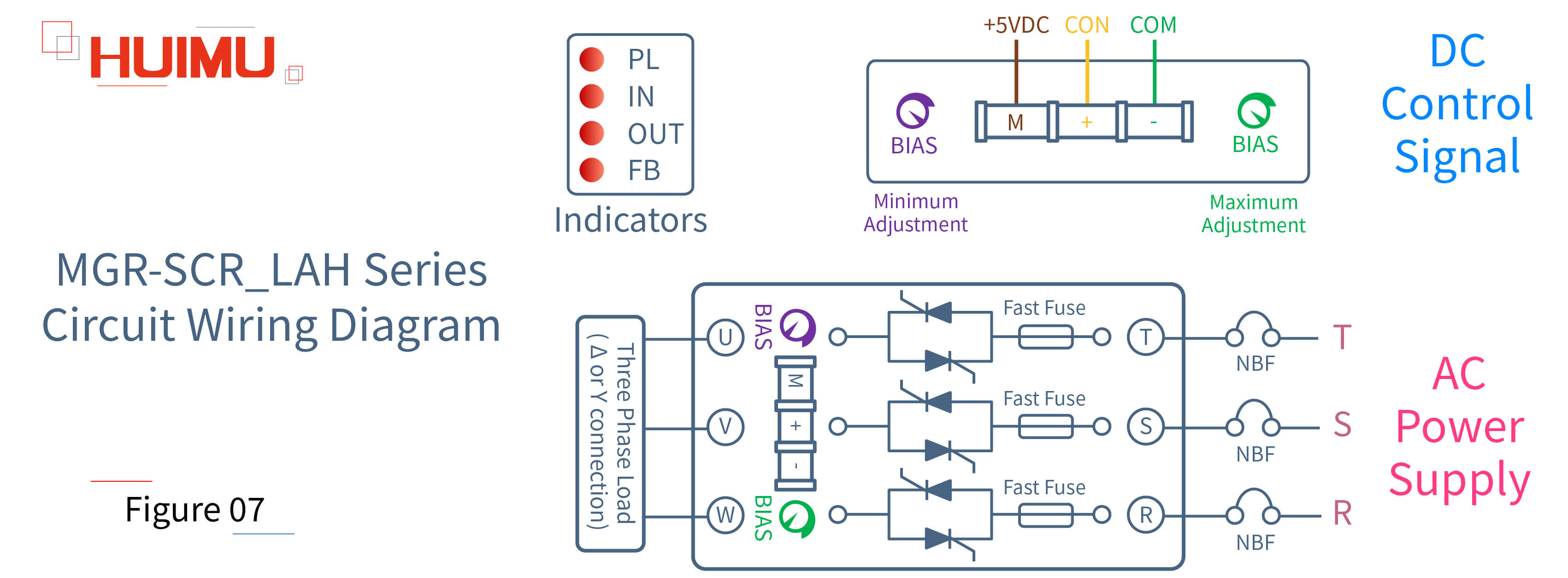
Compared with the basic type three phase AC solid state voltage regulator, the professional type three phase AC solid state voltage regulator has more functions and is more suitable for harsh working environments. The input terminals (brown, yellow, and green) of the professional type three phase AC solid state voltage regulator can be connected depending on the control mode. The output terminals of the professional type three phase AC solid state voltage regulator are divided into two groups, one of which (R, S, T) is connected to the three phase power supply, and the other (U, V, W) is connected to the load. The control mode of the professional type three phase AC solid state voltage regulator can be divided into automatic control and manual control. In the case of automatic control, the green terminal is grounded and the yellow terminal is connected to the control device, so that the load voltage can be regulated and controlled by adjusting the control signal, which can be divided into E (0-5VDC), F (0-10VDC) and G (4-20mA) types. In the case of manual control, the green, yellow, and brown terminals can be formed into a potentiometer, so that the load voltage can be regulated and controlled by adjusting the potentiometer. It should be noted that the G (4-20mA) type solid state voltage regulator does not have manual control function. The professional type three phase AC solid state voltage regulator has two knobs BIAS, which are used to adjust the maximum and minimum values of the output voltage. In addition, the professional type three phase AC solid state voltage regulator is equipped with a set of LED indicators. When the professional type three phase AC solid state voltage regulator is connected to the three phase 380VAC power supply and powered on, the IN indicator will light up. When the professional type three phase AC solid state voltage regulator is connected to the load and operating stably, the OUT indicator will light up. When the working temperature of the professional type three phase AC solid state voltage regulator reaches the set temperature of the temperature controller, the PL indicator will light up. When the fast fuse of the professional type three phase AC solid state voltage regulator blows, the FB indicator will light up.
§2. How to wire Solid State Voltage Regulator Module?
2.1 Single Phase AC Solid State Voltage Regulator Module
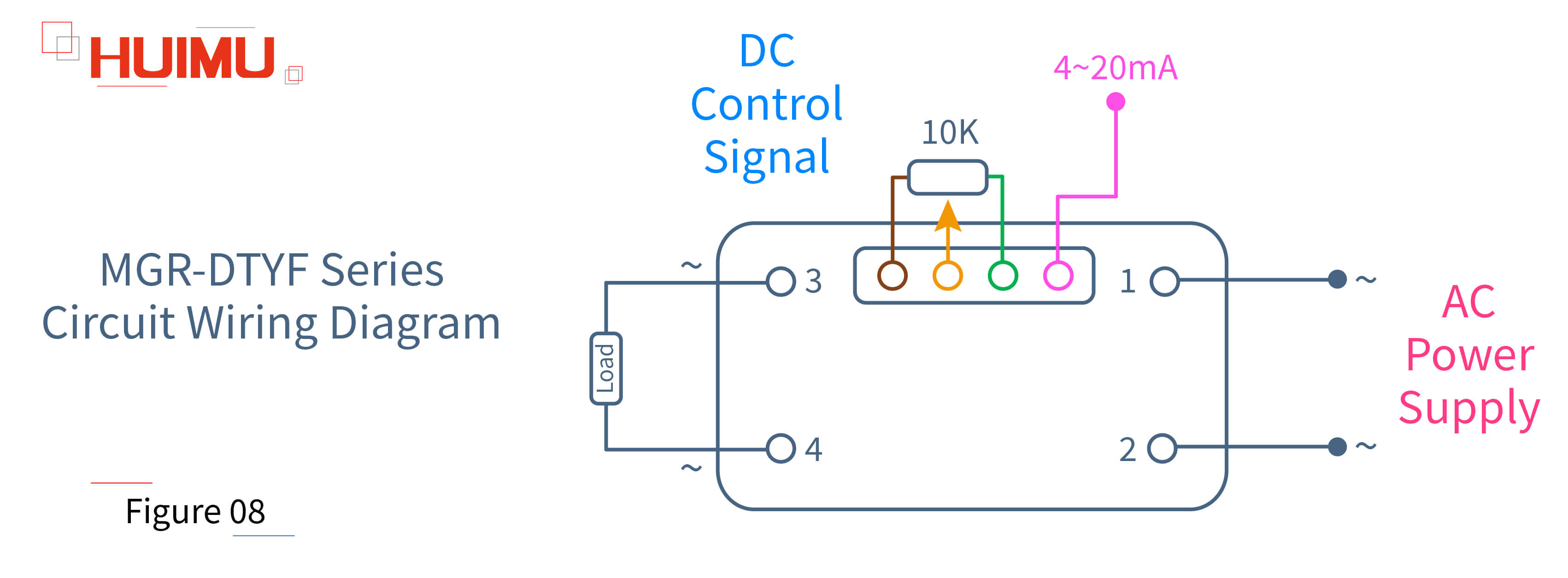
● MGR-DTYF Series
The negative feedback type single phase AC phase-shift solid state voltage regulator module has negative feedback voltage regulation function, which can output a stable load voltage even if the power supply voltage fluctuates abnormally. The negative feedback type single phase AC phase-shift solid state voltage regulator module has a built-in synchronous transformer, so there is no need to purchase an additional synchronous transformer. The input terminals (brown, yellow, green and pink) of the negative feedback type single phase AC phase-shift solid state voltage regulator module can be connected depending on the control mode. The output terminals of the negative feedback type single phase AC phase-shift solid state voltage regulator module are divided into two groups, one of which (PORT1 and PORT2) is connected to the single phase power supply, and the other (PORT3 and PORT4) is connected to the load. The control mode of the negative feedback type single phase AC phase-shift solid state voltage regulator module can be divided into automatic control and manual control. In the case of automatic control, the green terminal is grounded and the yellow terminal (or pink terminal) is connected to the control device, so that the load voltage can be regulated and controlled by adjusting the control signal, which can be divided into E (0-5VDC) and G (4-20mA) types. In the case of manual control, the green, yellow, and brown terminals can be formed into a potentiometer, so that the load voltage can be regulated and controlled by adjusting the potentiometer. It should be noted that the G (4-20mA) type solid state voltage regulator module does not have manual control function.
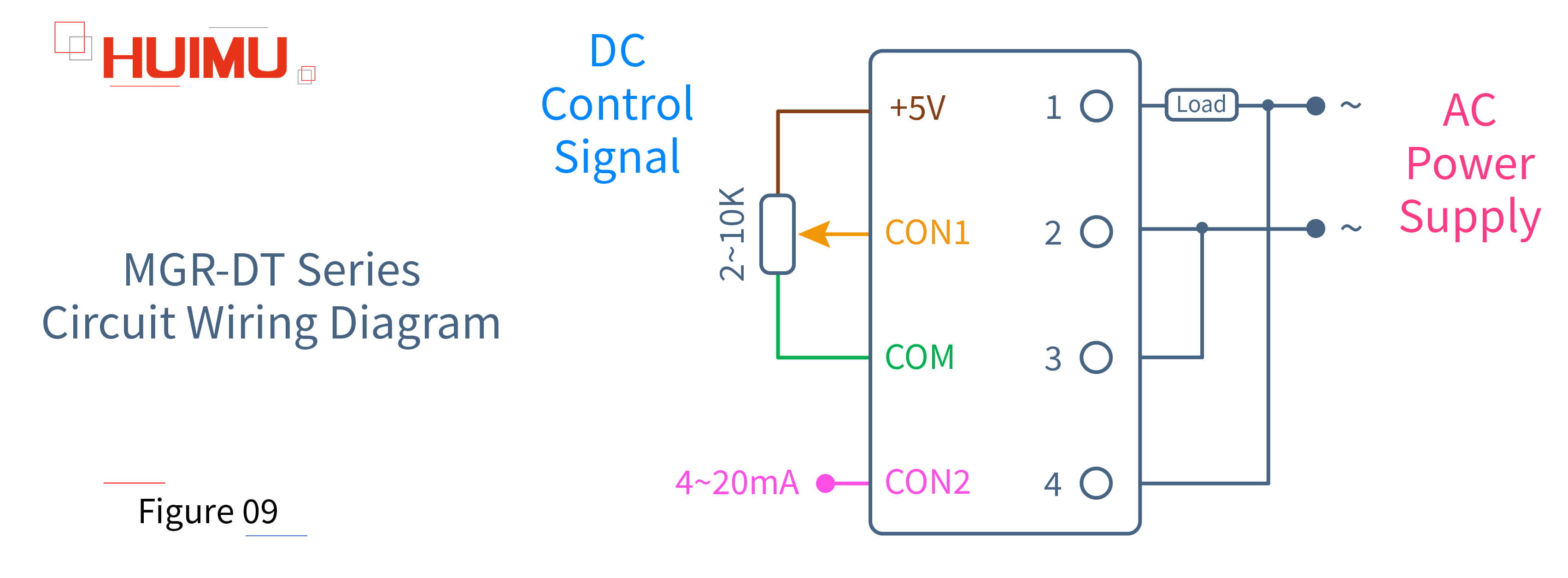
● MGR-DT Series
Compared to other single phase AC solid state voltage regulators and single phase AC solid state voltage regulator modules, the input and output circuits of the fully-isolated single phase AC solid state voltage regulator module are isolated, which can well protect the input circuit from the interference of the output circuit. The fully-isolated single phase AC solid state voltage regulator module has a built-in synchronous transformer, so there is no need to purchase an additional synchronous transformer. According to the rated voltage, the fully-isolated single phase AC solid state voltage regulator module can be divided into 220VAC and 380VAC types. According to the output waveform, the fully-isolated single phase AC solid state voltage regulator module can be divided into full-wave and half-wave types. Of course, the wiring is the same for these types. The input terminals (brown, yellow, green and pink) of the fully-isolated single phase AC solid state voltage regulator module can be connected depending on the control mode. The output terminals of the fully-isolated single phase AC solid state voltage regulator module are divided into two groups, one of which (PORT1 and PORT2) is connected to the single phase power supply and load, and the other (PORT3 and PORT4) is used to power the built-in synchronous transformer. The control mode of the fully-isolated single phase AC solid state voltage regulator module can be divided into automatic control and manual control. In the case of automatic control, the green terminal is grounded and the yellow terminal (or pink terminal) is connected to the control device, so that the load voltage can be regulated and controlled by adjusting the control signal, which can be divided into E (0-5VDC), F (0-10VDC), H (1-5VDC) and G (4-20mA) types. In the case of manual control, the green, yellow, and brown terminals can be formed into a potentiometer, so that the load voltage can be regulated and controlled by adjusting the potentiometer. It should be noted that the G (4-20mA) type solid state voltage regulator module does not have manual control function.

● MGR-DQZ Series
The fully-isolated single phase AC solid state controllable bridge rectifier voltage regulator module integrates the fully-isolated single phase AC solid state voltage regulator module and the single phase AC solid state controllable bridge rectifier, which not only has the function of voltage regulation, but also can change the output waveform through the internal controllable bridge rectifier. The fully-isolated single phase AC solid state controllable bridge rectifier voltage regulator module does not have a built-in synchronous transformer, so it is needed to purchase an additional synchronous transformer. The input terminals (brown, yellow, green) of the fully-isolated single phase AC solid state controllable bridge rectifier voltage regulator module can be connected depending on the control mode. The output terminals of the fully-isolated single phase AC solid state controllable bridge rectifier voltage regulator module are divided into two groups, one of which (PORT1 and PORT2) is connected to the single phase power supply, and the other (PORT3 and PORT4) is connected to the load. And PORT5 and PORT6 are used to power the built-in synchronous transformer. The control mode of the fully-isolated single phase AC solid state controllable bridge rectifier voltage regulator module can be divided into automatic control and manual control. In the case of automatic control, the green terminal is grounded and the yellow terminal is connected to the control device, so that the load voltage can be regulated and controlled by adjusting the control signal, which can be divided into E (0-5VDC), F (0-10VDC), H (1-5VDC) and G (4-20mA) types. In the case of manual control, the green, yellow, and brown terminals can be formed into a potentiometer, so that the load voltage can be regulated and controlled by adjusting the potentiometer. It should be noted that the G (4-20mA) type solid state voltage regulator module does not have manual control function.
2.2 Three Phase AC Solid State Voltage Regulator Module
● MGR-STY Series
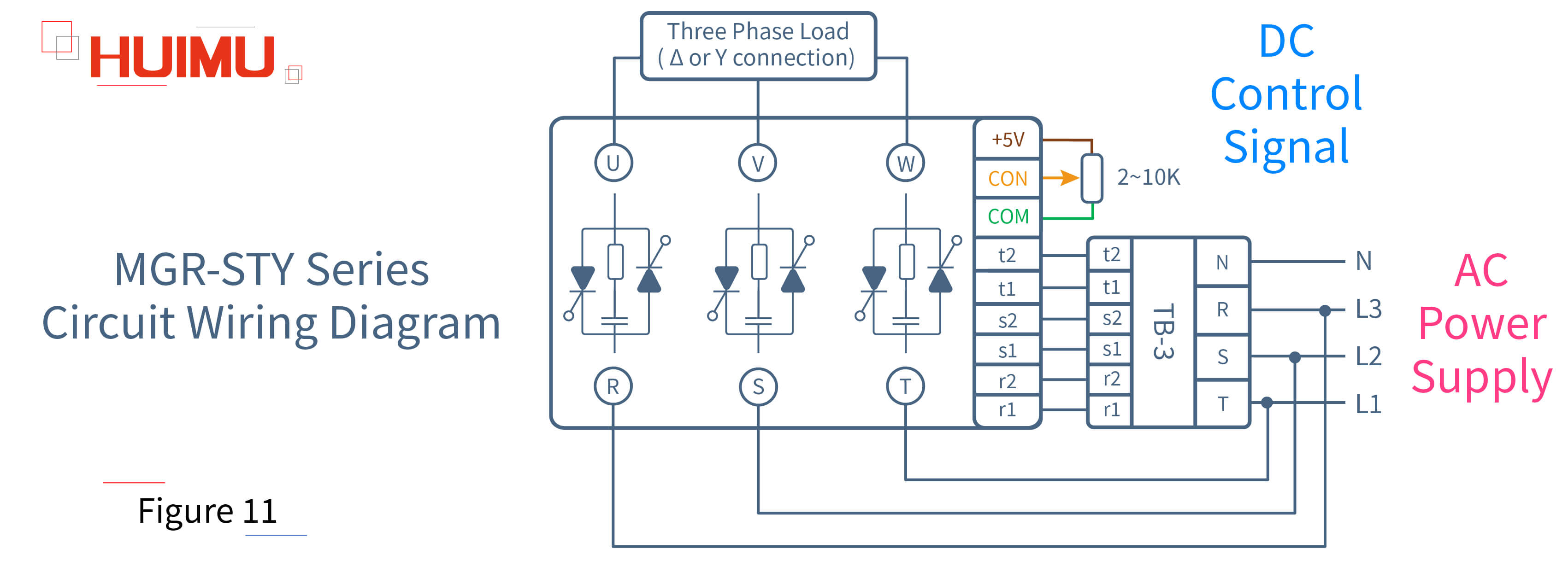
Compared to other three phase AC solid state voltage regulators and three phase AC solid state voltage regulator modules, the input and output circuits of the fully-isolated three phase AC solid state voltage regulator module are isolated, which can well protect the input circuit from the interference of the output circuit. The fully-isolated three phase AC solid state voltage regulator module does not have a built-in synchronous transformer, so it is needed to purchase an additional synchronous transformer TB-3. The input terminals of fully-isolated three phase AC solid state voltage regulator module are divided into two groups, one of which (brown, yellow, green) is connected depending on the control mode, and the other (r1, r2, s1, s2, t1, t2) needs to be connected to the corresponding port on the TB-3. The output terminals of the fully-isolated three phase AC solid state voltage regulator module are divided into two groups, one of which (R, S, T) is connected to the three phase power supply, and the other (U, V, W) is connected to the load. The control mode of the fully-isolated three phase AC solid state voltage regulator module can be divided into automatic control and manual control. In the case of automatic control, the green terminal is grounded and the yellow terminal is connected to the control device, so that the load voltage can be regulated and controlled by adjusting the control signal, which can be divided into E (0-5VDC), F (0-10VDC), H (1-5VDC) and G (4-20mA) types. In the case of manual control, the green, yellow, and brown terminals can be formed into a potentiometer, so that the load voltage can be regulated and controlled by adjusting the potentiometer. It should be noted that the G (4-20mA) type solid state voltage regulator module does not have manual control function.

Get in touch with us now!
Please select the message type and fill in the contact form in English. Thank you!
*Please check the trash box of your mailbox, if you do not receive our email.


