
How to wire the Multi-Channel Solid State Relay?
Multi-channel solid state relays have multiple control loops inside, so they can control more loads than single-channel solid state relays. In other words, only one multi-channel solid state relay can complete the work that two or more single-channel solid state relays can do, which greatly reduces the cost of purchase and use, and also improves the space utilization and work efficiency of the equipment. According to the number of loads, multi-channel solid state relays can be divided into dual-channel solid state relays and five-channel solid state relays. Depending on the control mode, dual-channel solid state relays can be further divided into single pole double throw (SPDT) solid state relays and double pole single throw (DPST) solid state relays. The SPDT solid state relay uses one control signal to control two loads that are operating in opposite states. The DPST solid state relay is similar to two single pole single throw (SPST) solid state relays and is capable of controlling two loads independently. The five-channel solid state relay is often referred to as the five pole single throw (FPST) solid state relay, which is similar to five SPST solid state relays and is capable of controlling five loads independently. However, multi-channel solid state relays have limited internal space and therefore cannot accommodate high power switching components, and therefore operate at relatively low power levels and are not suitable for high power loads. Of course, it is important to confirm whether the specifications meet your requirements before installing and using our multi-channel solid state relays, such as input current, input voltage, output current, and output voltage. Through this article you will learn the circuit wiring diagrams of our multi-channel solid state relays.
You can quickly navigate to the chapters you are interested in through the Directory below, and the Quick Navigator on the right side of the browser.
CONTENTS
§1. How to wire the Dual-Channel Solid State Relay? |
§2. How to wire the Five-Channel Solid State Relay? |
§1. How to wire the Dual-Channel Solid State Relay?
1.1 SPDT Solid State Relay
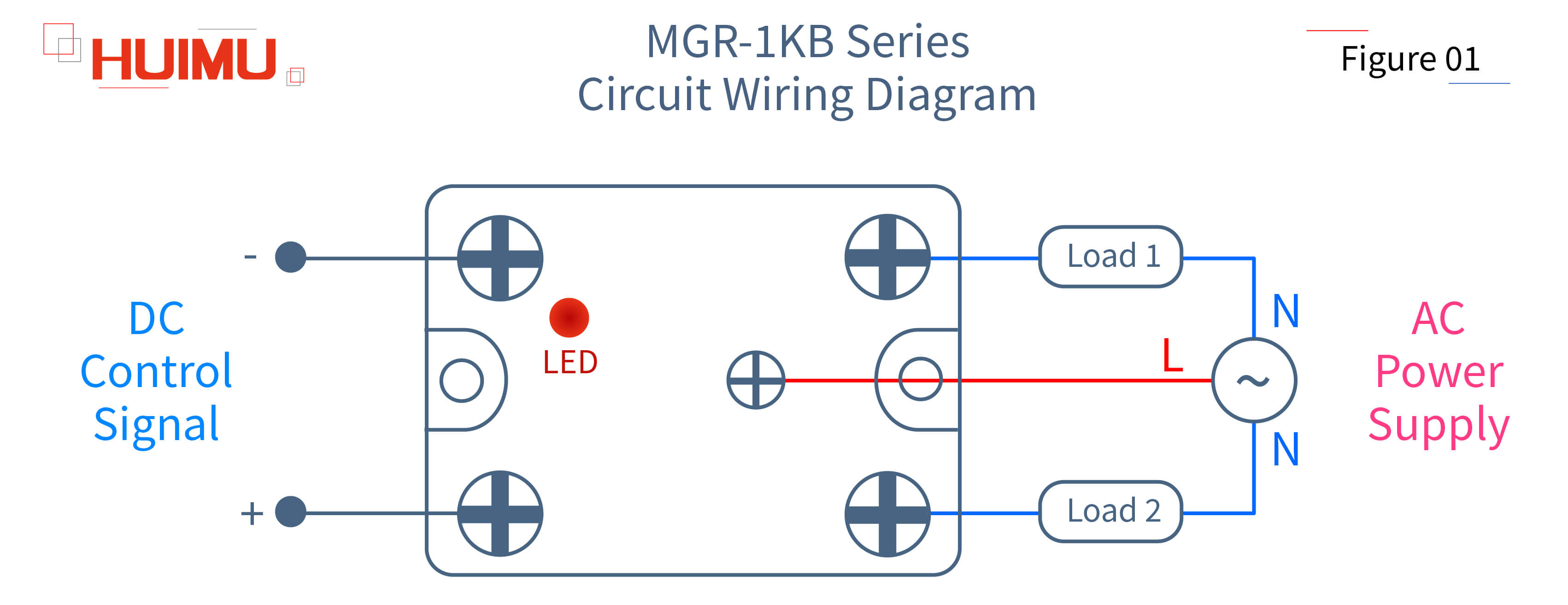
● MGR-1KB Series
The SPDT DC to AC dual-channel solid state relay is capable of controlling two single phase AC loads with opposite operating states. The two input terminals of the SPDT DC to AC dual-channel solid state relay are connected to the control signal device. The three output terminals of the SPDT DC to AC dual-channel solid state relay are connected to the two loads. Load1 is connected to the normally closed terminal, and Load2 is connected to the normally open terminal. They share a common terminal. When Load1 is working, Load2 will not work, and when Load2 is working, Load1 will not work. The LED shows the operating status of Load2. Due to the limited heat dissipation capacity, the load capacity of SPDT solid state relays is usually not large.
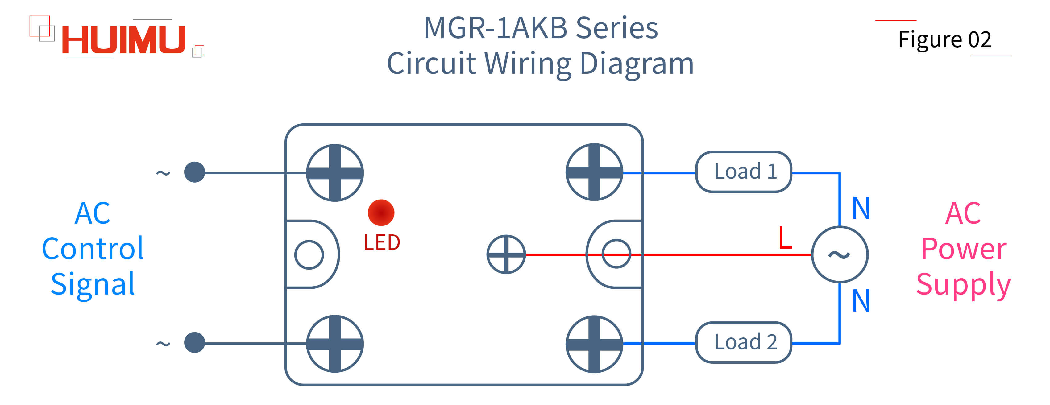
● MGR-1AKB Series
The SPDT AC to AC single phase solid state relay is capable of controlling two single phase AC loads with opposite operating states. The two input terminals of the SPDT AC to AC dual-channel solid state relay are connected to the control signal device. The three output terminals of the SPDT AC to AC dual-channel solid state relay are connected to the two loads. Load1 is connected to the normally closed terminal, and Load2 is connected to the normally open terminal. They share a common terminal. When Load1 is working, Load2 will not work, and when Load2 is working, Load1 will not work. The LED shows the operating status of Load2. Due to the limited heat dissipation capacity, the load capacity of SPDT solid state relays is usually not large.
1.2 DPST Solid State Relay
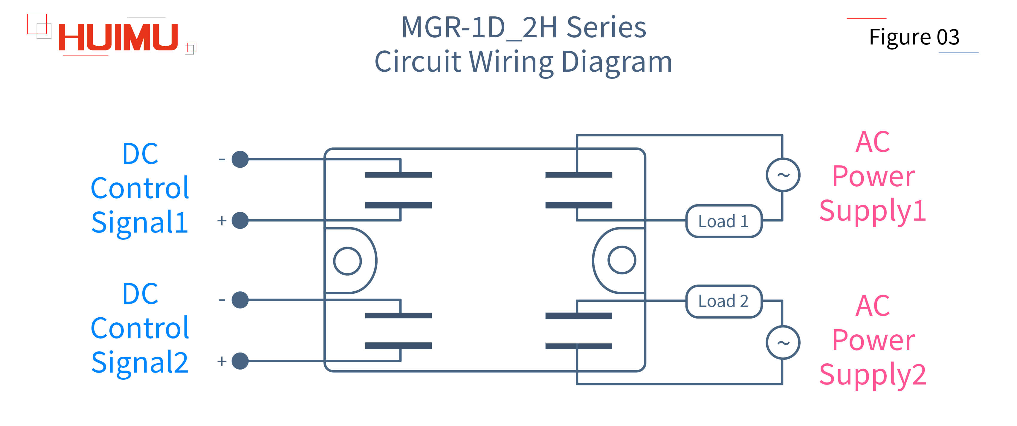
● MGR-1D_2H Series
The DPST DC to AC dual-channel solid state relay integrates two SPST DC to AC single-channel solid state relays into a standard package, which means that two completely different loads can be controlled with only one solid state relay. Unlike SPDT solid state relays, DPST solid state relays have two control circuits and two output circuits. The four input terminals of the DPST DC to AC dual-channel solid state relay are connected to two control signal devices. The four output terminals of the DPST DC to AC dual-channel solid state relay are connected to two load power supplies. Since each control signal controls a separate load, the two loads of the DPST solid state relay work independently and do not affect each other. Due to the limited heat dissipation capacity, the load capacity of DPST solid state relay is usually not large. The MGR-1D_2H series DPST DC to AC dual-channel solid state relay utilizes a insert mounting method, which means that the wires are connected to the solid state relay through insert reed terminals.
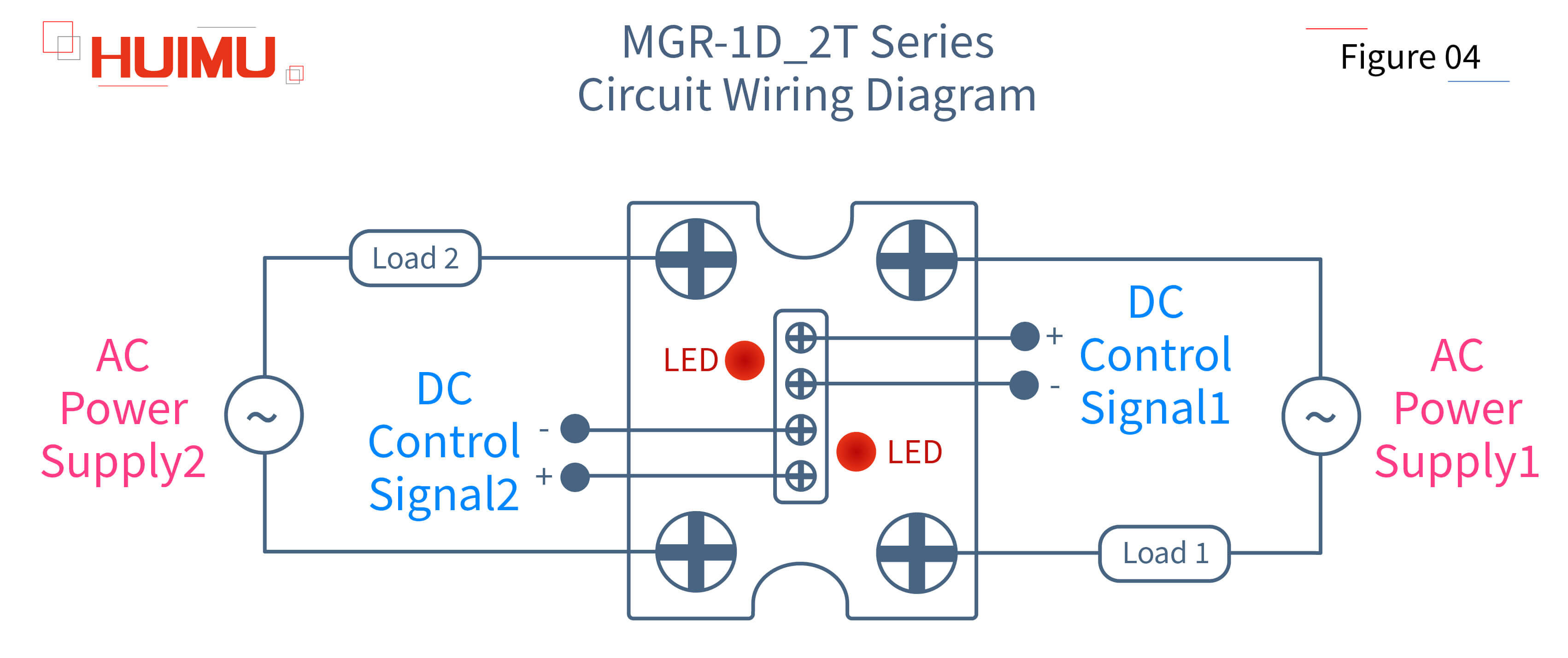
● MGR-1D_2T Series
The DPST DC to AC dual-channel solid state relay integrates two SPST DC to AC single-channel solid state relays into a standard package, which means that two completely different loads can be controlled with only one solid state relay. Unlike SPDT solid state relays, DPST solid state relays have two control circuits and two output circuits. The four input terminals of the DPST DC to AC dual-channel solid state relay are connected to two control signal devices. The four output terminals of the DPST DC to AC dual-channel solid state relay are connected to two load power supplies. Since each control signal controls a separate load, the two loads of the DPST solid state relay work independently and do not affect each other. Due to the limited heat dissipation capacity, the load capacity of DPST solid state relays is usually not large. The MGR-1D_2T series DPST DC to AC dual-channel solid state relay utilizes a crimp mounting method, which means that the wires are connected to the solid state relay through crimp terminals.
§2. How to wire the Five-Channel Solid State Relay?
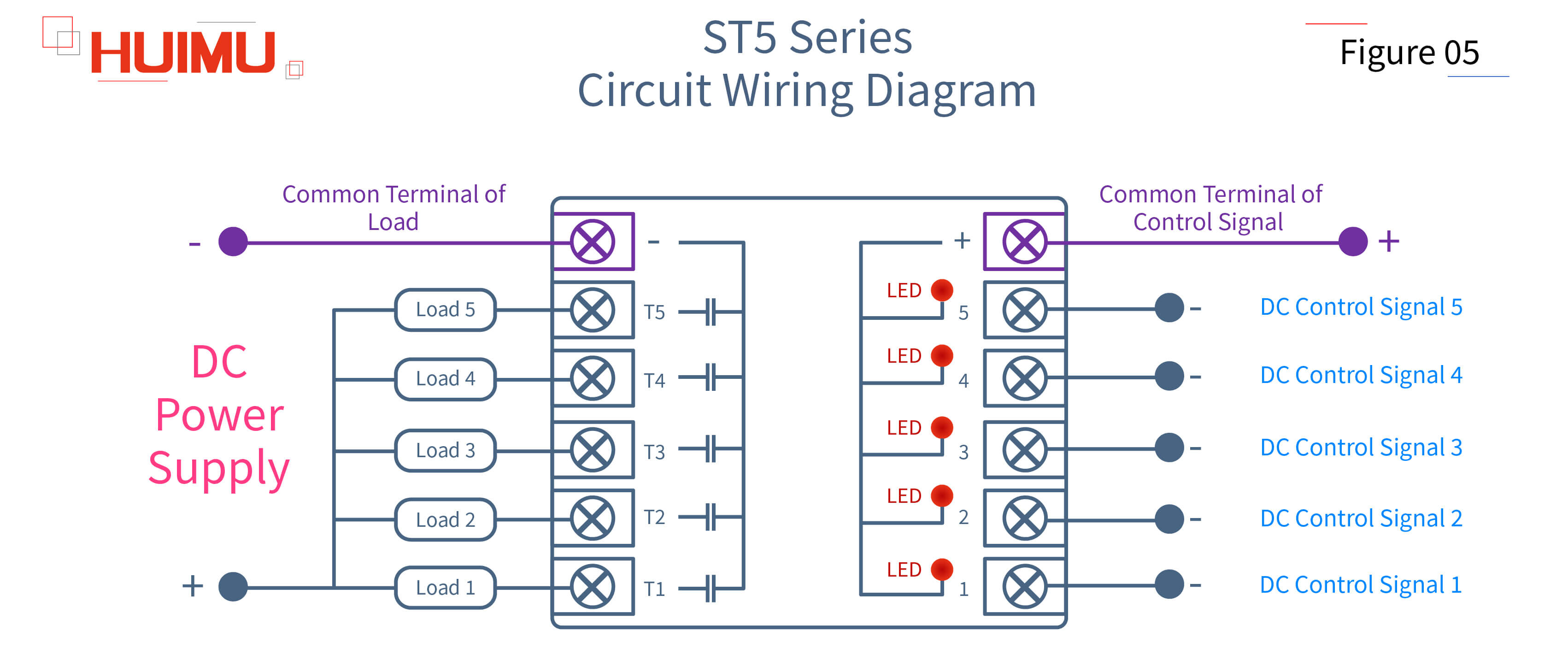
● ST5 Series
The FPST DC to DC five-channel solid state relay integrates five SPST DC to DC single-channel solid state relays, which means that five completely different loads can be controlled with only one solid state relay. The six input terminals of the FPST DC to DC five-channel solid state relay are connected to five control signal devices and one common terminal respectively. The six output terminals of the FPST DC to DC five-channel solid state relay are connected to five load power sources and one common terminal respectively. Since each control signal controls a separate load, the five loads of the FPST solid state relay work independently and do not affect each other. Five LEDs show the operating status of each load separately. Due to the limited heat dissipation capacity, the load capacity of FPST solid state relays is usually not large.
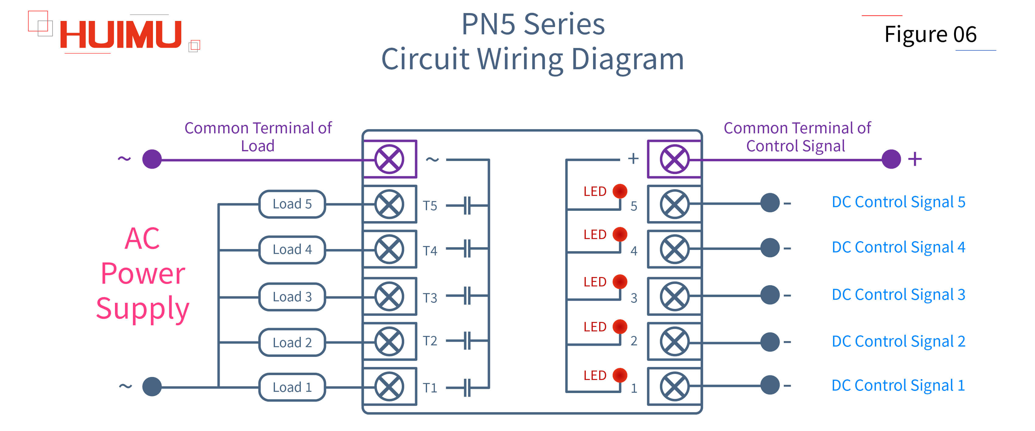
● PN5 Series
The FPST DC to AC five-channel solid state relay integrates five SPST DC to AC single-channel solid state relays, which means that five completely different loads can be controlled with only one solid state relay. The six input terminals of the FPST DC to AC five-channel solid state relay are connected to five control signal devices and one common terminal respectively. The six output terminals of the FPST DC to AC five-channel solid state relay are connected to five load power sources and one common terminal respectively. Since each control signal controls a separate load, the five loads of the FPST solid state relay work independently and do not affect each other. Five LEDs show the operating status of each load separately. Due to the limited heat dissipation capacity, the load capacity of FPST solid state relays is usually not large.

Get in touch with us now!
Please select the message type and fill in the contact form in English. Thank you!
*Please check the trash box of your mailbox, if you do not receive our email.


