
Products

Electronic Switch
● PCB Mount Solid State Relay
● Panel Mount Solid State Relay
● Single Phase Industrial Solid State Relay
● Three Phase Industrial Solid State
Relay
● Single Phase Compact Solid State Relay
● Three Phase Compact Solid State Relay
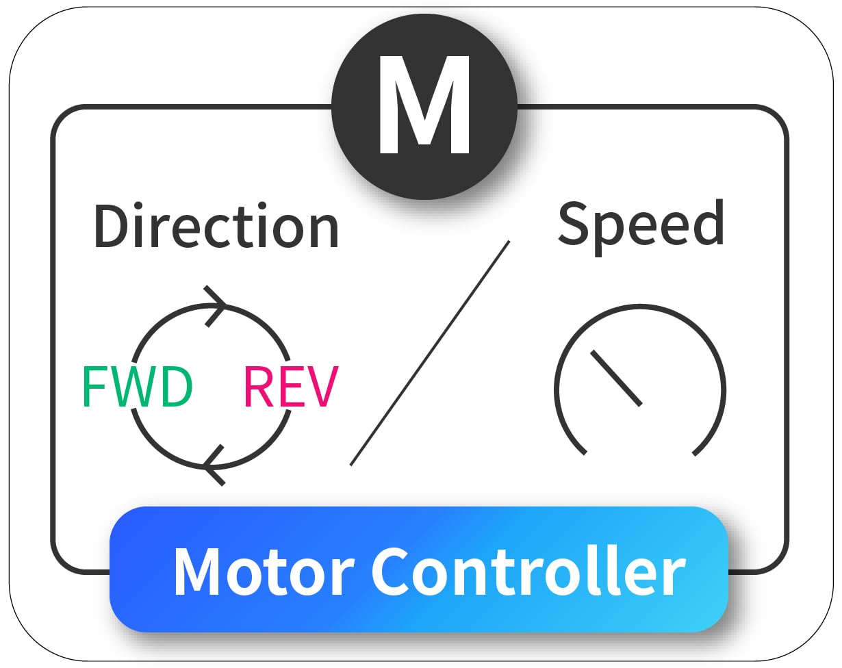
Electrical Motor Controller
● Bi-directional Motor Rotation Controller (FWD/REV)
● Motor Speed Controller
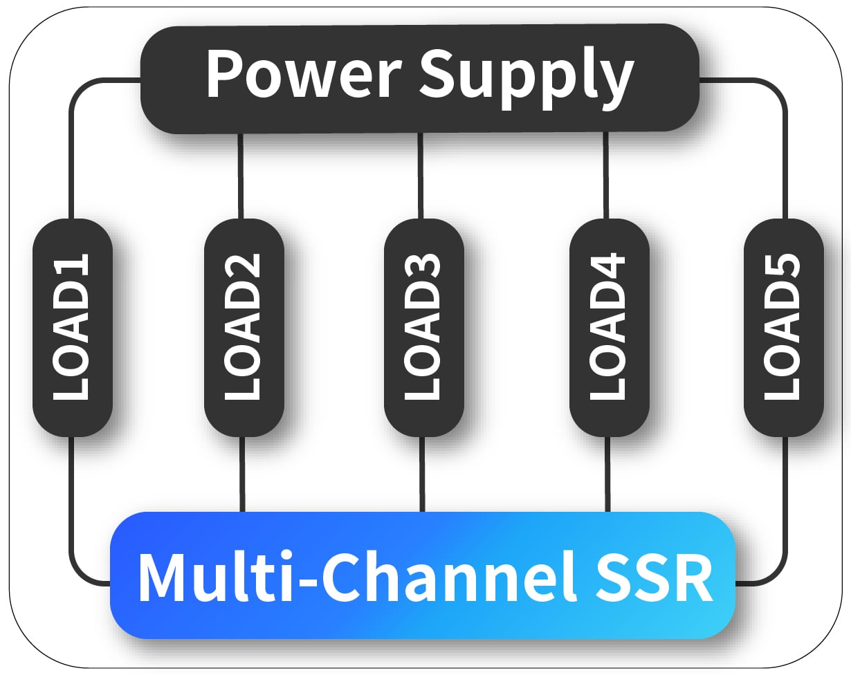
Multi-load Switch
● SPDT Solid State Relay
● DPDT Solid State Relay
● Dual Channel Solid State Relay
● Three Channel Solid State Relay
● Five Channel Solid State Relay
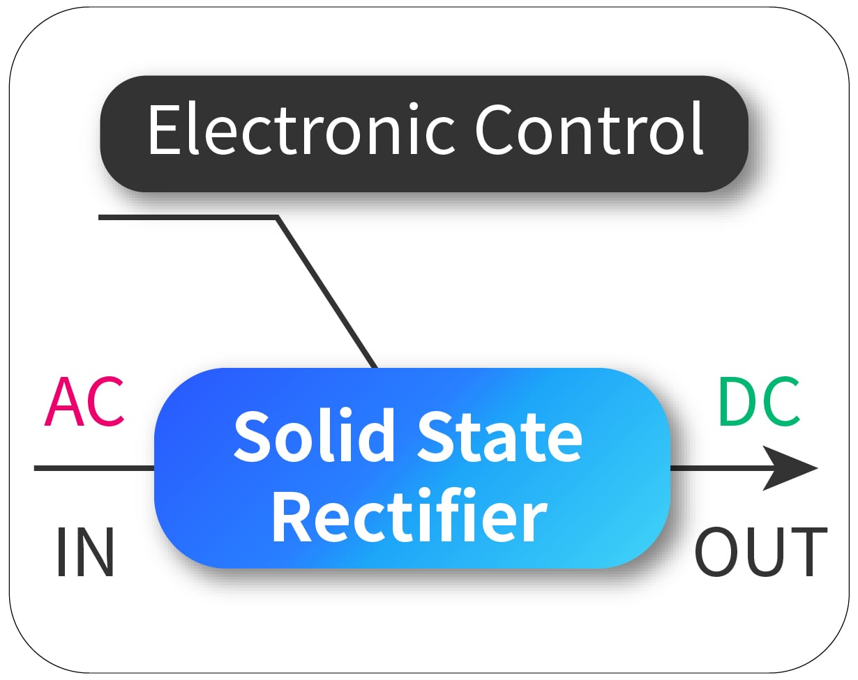
Solid State Rectifier
● Solid State Rectifier Relay
● Solid State Bridge Rectifier
● Solid State Rectifier Module

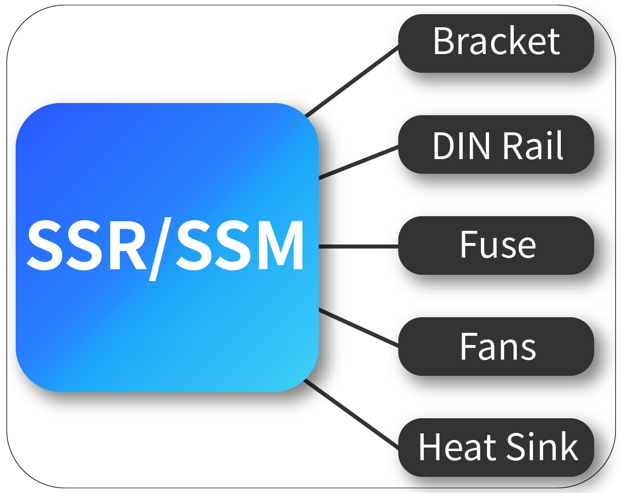
SSR/SSM Accessories
● Solid State Relay Heat Sink
● Solid State Module Heat Sink
● DIN Rail Bracket
● DIN Rail
Get in touch with us now!
Please select the message type and fill in the contact form in English. Thank you!
*Please check the trash box of your mailbox, if you do not receive our email.


